fbpx

Kontakt:

Lelit Mara X V2 Gicar Internals

This page deals with the internal electronics of the famous Italian Expresso Machine Mara X V2

Because of its popularity many gadgets and tools have been developed in the open source community, however some of them are lacking good engineering practices or are simply wrong.


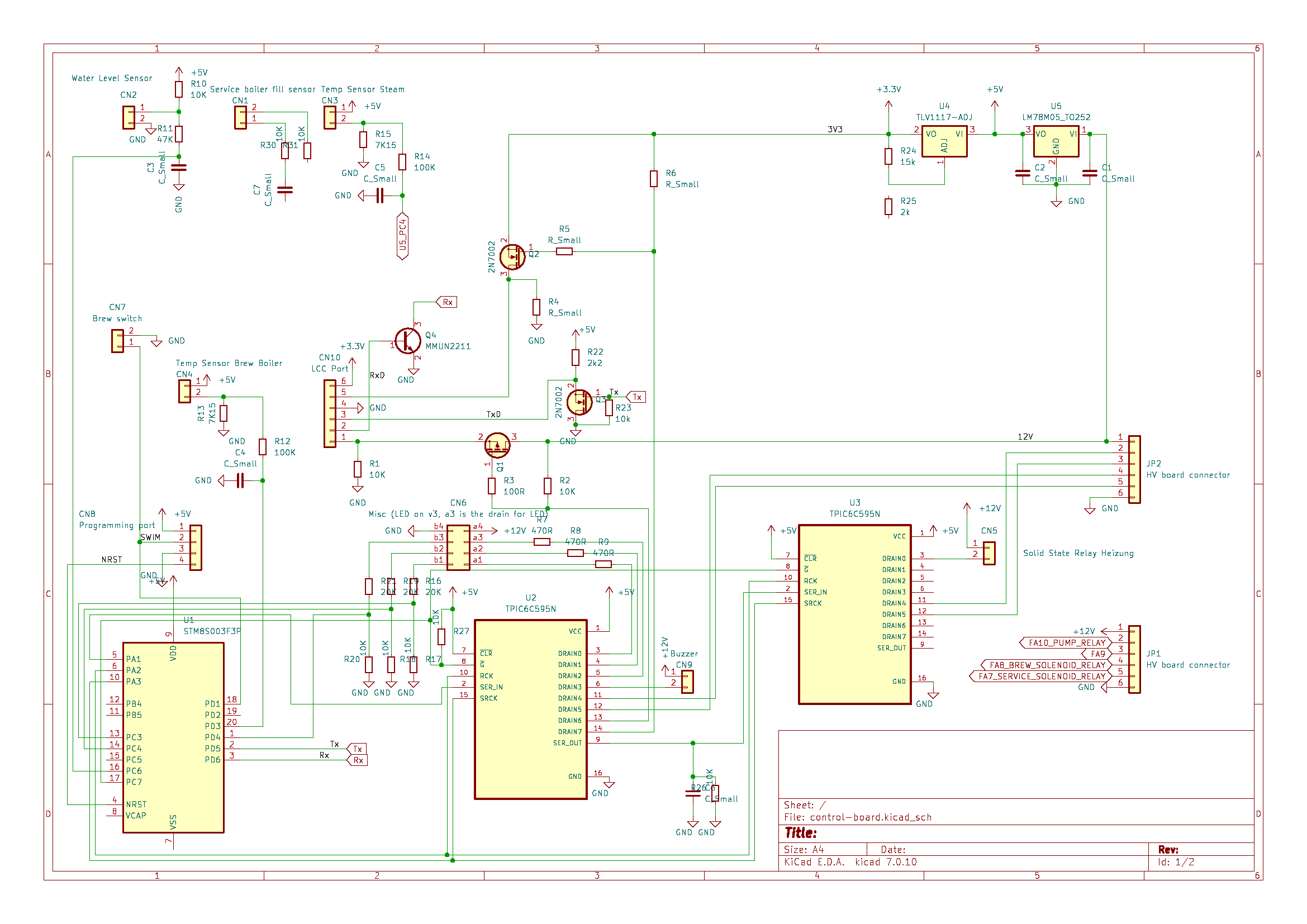
The core of the Gicar is a 16MHz STM8 Processor, which contains 8k Byte of Flash and 128 Byte of EEprom. Not much, but enough for this job. This is one of the cheapest processors around. Just as a comparison: an ESP32 WROOM Module is at least 10 times quicker and has 512 times the amount of Flash Memory, contains WiFi, Bluetooth, AD Converters, lots of IOs and is available for 5€.
It should be fun writing a new OS for the MaraX on that just replacing the STM8 ... but my time is currently limited.

I was able to dump both content of Flash & Eeprom from my STM8 Gicar Processor for further analysis. With this information it should be possible to update the Gicar to newer Firmware versions, as long the PCB Hardware is the same.

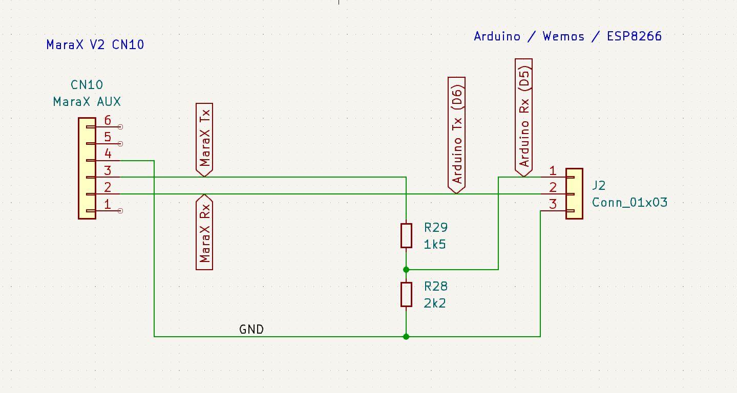
During the weekend I  looked through the code of the Gicar module, but there seems no Rx functionality implemented. This means there's no option to send any data to the Gicar for hidden commands, wakeup or upgrade. The Rx line could therefore be omitted.
The Code was complied using IARs EWSTM8 compiler. At the begin of the code is a huge Table, which seems to contain the curves for the temp sensors.

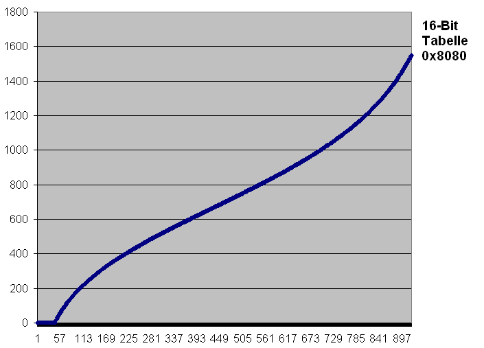
The Table contains 921 Values and togehter with the compiler Runtime, already half of the availabel flash memory is used.

I'm also working on reverse engineering some of the Gicar circuits to better understand what it is doing. I will update this page periodically.


When interfacing the Mara X Gicar with external displays or interfaces, a lot of false information is circulating on the web.
Here is how to do it correctly:
The Gicar control module is a 5V system, while most Arduinos / Wemos / ESP8266 Modules work at 3,3V. The latter ones are sensitive on their IOs and NOT 5V TOLERANT!
In other words: it migth work interfacing the serial Interface of an Ardudino and Gicar directly, but it is out of spec. You are already far above the allowed signal level when providing a 5V Signal to a 3,3V Input, so nobody can tell, how long this migth work.
On top of that, most connection Diagrams I have seen are fundamentally wrong!
Please see picture above about the correct pinout of th Gicar AUX Connector (CN10).
Because of the wrong wiring shown on most web pages, people only made it work by using even the wrong code.
The MaraX serial interface communicates "inverted" ... so a logic 1 is 0 and vice versa. The Arduino serial routine needs to take care of that!

In most code I've seen, the serial port is used this way (wrong!)

// initialize the serial port
SoftwareSerial mySerial(D5, D6);

This is the correct way:
// initialize the serial port
SoftwareSerial mySerial(D5, D6, 1);
The 1 at the end tells the function to use inverted logic. This is the ONLY CORRECT WAY to do it!

Above, you can see the simple schematic, how to safely interface the MaraX Gicar to any 3,3V System. Just use a voltage divider on the MaraX Tx line and you are done. I will reduce the 5V signals sent by the MaraX to 3,3V.
The 3,3V Tx Signal sent by the Arduino is enough for the MaraX Rx input, as there's a special digital input Transistor (MUN2211) on the Gicar PCB taking care of this. Please note that it is indispensable connecting both ground points!
For providing power for your external display, I recommend using Pin 1 of the Buzzer Connector next to the AUX Connector. On this Pin there are unregulated 12V from the MaraX Power Supply which can be used for a simple StepDown Converter producing 5V for an Arduino or Wemos D1 Module.

Above you can see an incomplete schematic of the Gicar internals.
All important parts are covered and there was no need to get any deeper into it.
In case you need the KiCad file or bigger picture, just send me a mail.
Also in case you need the Gicar Processor Flash & Eeprom Data, just let me know.
Both files are available as Bin or Intel Hex. I also produced a raw Assembler File.

Here a few Links to projects who did it wrong: (in principal all did it wrong and copied the errors of each other). It's hard to see so many people able to write code, but don't know about the hardware.

https://github.com/RedNomis/MaraXObserver
https://github.com/SaibotFlow/marax-monitor
https://github.com/DiSanzes/Mara-X2-ShotTimer/tree/main
https://www.reddit.com/r/Coffee/comments/hfsvep/data_visualisation_lelit_marax_mod/
https://github.com/zierroff/MQTT-MaraX

One Reply to “Lelit Mara X V2 Gicar Internals”

Comments are closed.